 |
 |
|
|
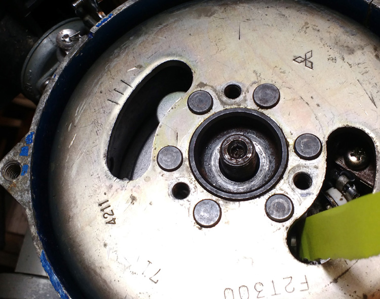
Update to the Suzuki engine rebuild - Oct 2018 Its been a while - but I have been up to other things - never mind. Last year I serviced the Suzuki at home - fitted a new tap, had the head off and checked the water jacket - impellor etc. Ran it and drained the carb and cleaned it. Sat in the locker over the winter it must have suffered - damp I suppose.Tried to start if last week and it would not spark. At home it still would not start. Also - I was getting a dead short between the coil side of the points when open - even when insulated apart with card. Off with the flywheel. A sorry sight inside - where the magnets had rusted and dropped crap evenywhere all over the points and baseplate. I decided to remove the condensor ( suspecting it for making the short ). Cleaned everything up - flywheel, baseplate etc. Checked and cleaned the points. Flywheel back on loose - points on with no condensor - and turned it over with the emergency pull cord - big fat spark ? BUT - still I had continuity to baseplate/ground from either side of the points - open or closed ? Mystfiied - I replace condensor - big fat spark. I hit the internet on a quest of magneto education - and quickly find my own posts of some years ago on a Seagull outboard forum ! Any way - this is the situation. On these magneto points - the coil side of the points is wired to the primary coil element - and this element goes to ground. Also wired to ground is the secondary element ( that goes to the plug for the spark ) The primary has 'virtual continuity' - ie its only 0.5 ohm - so is very difficult to tell from 0 on cheap multimeters. This is what skews the reading of the points to ground. The secondary should be giving you a reading of approx 4000 ohm - from ht lead to baseplate/ground - or from ht lead to points wire. The secondary coils is long and fine and this creates the high voltage spike for the spark. I also learned in all this ( I will post it soon ) of how to properly test a condensor. One can do it with some clever stuff with a multimeter. You basically drain it ( by testing its voltage ) - then charge it by tresting it for amps ( puts some charge in ) then checking again the volts to see if it held power. They are basically a sort of 'volt sink' so act like small battery. I am dumb with electronics - as you can probably tell ! Parts Only the very early DT2's had points - they are not even covered in the manual I have. Points gap is 0.3 - 0.4mm I read that even if points seem really nice condition - what affects them a lot is wear on the cam. If this reduces in size too much it affects the relationship between the magneto charge into the coil - so even if the gap is right and the contacts not worn they can still be causing problems ! Points for a DT2 are not easy to source - but if you check online at Brownes Point Marine - they have all the Suzuki outboard parts fiches - so one can get the part no's. Search the part no - and you will find them listed on Motor cycle factors. motorcyclespareparts.eu have them listed - thwy are rare parts to aquire ! Coil - is 32140-98431 - £58 inc vat condenser - 32341-98430 - £13 points - 32240-98034 - £18.95 also - baseplate gasket is listed on these sites well cheaper than usual ( all genuine parts ) I also found some info from an old version of the DT2 manual on timing. On the DT2 flywheel there are three lines - and a notch in the casing above the carb. Checking tdc with a depth guage ( a digital caliper will do it ) the three lines represent 5, 10 a 15 deg before. My original baseplate setting was giving a points opening ( use a cigarette paper trapped in the closed points - when it releases ) of just past the first of the three lines (13 deg before ) This manual gave the magic figure for piston crown below tdc - of 0.032" as a firing point. I checked this and it was spot on to my original baseplate set up. On the base plate - one fixing hole has three lines on it. The centre line in line with the centre of fixing screw is where my baseplate was fixed. That seems to be 'factory' setting. Lets get his clear - Flywheel spins clockwise - tdc is to the LEFT of the lefthand line - by the width of the other lines ! ie - right hand line is 15 deg before ( on the flywheel lined up with the notch - the lines are 5 deg increments ) So - the middle line lined up is 10 before - and the left line with the notch 5deg - with TDC opposite a position (blank ) @ 5 deg left of the left line. Its confusing !
empty - pics are 800 - seem to be ok in firefox empty empty - table 0 0 space 6 - colour NO - main cell col 3, span 1 colour NO |
||